This week we talking final project only, answering some questions.
Requirements
Answer these questions:
What does it do?
It's a moon phase tracker that tracks the phase. It's largely inspired by Simone Grietz's video and her collaboration with dina Amin. It used the mechanisms of flap display. It uses an API which sends the state of the moon. The device will connect to the NTP server to fetch the current date and send the date to the API. while It gets the phase back the motor will rotate the flaps until it homes meaning displays a welcoming flap. Then once it gets back the data move to the flap number that has the drawings of this phase. The device will have a display that shows the name of the phase
Who's done what beforehand?
There are many people who have done similar projects, the most notable one is Simone Grietz's video on YouTube.
mostly people use the split flip mechanism in making clocks most notably here this open source project which Amr recommended me to check out. I didn't find any lunar phase trackers in Fab Academy archived projects but I found I lot of Lunar clocks that use different ways to display time and moon phase
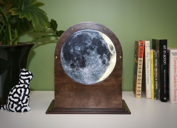
Image from Instructables
What materials and components were used? &Where did they come from? & How much did they cost?
BOM
| Component & Materials | Quantity | Link/supplier | Price |
|---|---|---|---|
| 3mm Wood | scraps | Local distributer | -- |
| 3mm Black Acrylic 100*60cm | 0.5 | SpiroGlass | 1500EGP |
| PLA | 0.25KG | From the lab | 250 EGP |
| Capacitors | ~5 | available at the lab | 0.5 EGP per unit |
| Resistor | 10 | available at the lab | 0.5 EGP per unit |
| ESP32-Wroom | 1 | Here | 340EGP |
| Switches | 2 | available at the lab | 2EGP per Unit |
| NEMA16 Stepper Motor | 1 | here | 245 |
| TMC 2208 | 1 | Here | 195 EGP | PinHeaders | ~ | available at the lab | -- |
| Voltage Regulator | 1 | here | |
| Adaptor 12v 3A | 1 | available at the lab | -- |
| Screws and Washers (M3,M4,M5) | 1 | Available at the lab | ~50ُ |
| Copper tape | 1 | Available at the lab | ~~ |
| LCD I2C 16x2 | 1 | available at the lab | 0 |
What did you design?
- Frame (Laser cut)- I design a one compartment design to test the stepper movement and fittings with wood but I will - in the process of- design two compartment design: one for the electronics and one for the display of flaps. It's largely inspired by the splitflaps mechanism I mentions above.
- Motor shaft (3D Printed)
- Flaps (Laser cut + sticker Printed)
- Stepper Driver + LCD pcb (done)
- Reed sensor pcb
What processes were used?
I will use the following processes:
- 3D Printing: Printing the shaft
- CNC Milling: milling the pcbs
- Laser Cutter: the Frame & the flaps
What parts and systems were made?
I made the mechanism draft shaft and flaps compartment. I'm experimenting with paper flaps which I'm concerned is becoming futile. I'm trying now acrylic 3mm which is abit heavy on the motor but we'll see.
I fabricated a pcb but I missed up the capacitor footprints and now once it got working the voltage regulator popped :'''[[. I'm thinking of giving up on the neopixel because the voltage regulator we have right now its max current is 1A while I'm powering the stepper and the neopixel with 3 using the power supply.
What questions need to be answered? what questions need to be resolved?
- How to design a simple reed switch with pinheaders only and can I discard the pull_up resistor?
- What materials to use that aren't heavy and aren't easily broken for the flaps?
- Should I discard the neopixel and work with an LCD instead?
- How to design the electronics compartment to not be wire hell?
- Homing he stepper with the reed? where should it be placed in the design for it to detect the magnet?
- What to write on the welcoming flap?
- WHAT SHOULD IT BE NAMMMMMMED?
What worked? What didn't?
- fetching the NTP data worked (backup plan)
- fetching and parsing the data from FarmSense worked
- Moving the motor once a certain value from the API returned worked
- Design fittings for the shaft good
What didn't work is the neopixel and the voltage regulator. I need to redesign the pcb to fix the capacitor footprints and use a better voltage regulator. i will not have time to mnake an UI like I intinaly intended but that's okay
How was it evaluated?
- The Lunar tracker first rotated to show a welcome flap.
- The project should fetch the date and lunar phase and display it on a LCD.
- The project show the current phase via visual way using spliflap mechanism
- The date can be moved forward and backwards and moves accordingly to show the phase at that date.
What are the implications?
I believe this project and other similar projects help us to mend the broken relationship with time. We used to look up so much at the heavens and now all I see is skyscrapers and light pollution. I took a video showcasing that seeing the moon is not that Mend a lost wound with the sky. I like the sound of this purpose. My purpose.
This is what I mean!
Apart from philosophical and romantic talk I think this project is a good way to learn about the splitflap mechanism, learn different phases of the moon and to and how they affect us and maybe can go to be used a Mensturation Cycle Tracker for mensturating people. Who KNOWS SO MANY Possibilities!!
what tasks have been completed? & what tasks remain?
what have you learned?
I learned allllot about pcb design and power management.I designed my first mechanism and dare I say working one! I learned that reed switch break so easily fr what is that I broke like 3 while I was just soldering. I learned about calibrating sensors and capacitve touch! I learned that a supportive community is all you need and I have a madwoman alter ego when I operate on 1h sleep! Funsies